Note
Screenshots may differ slightly depending on software version.
Design-Space Augmentation
Introduction
Experimenters, particularly those doing industrial R&D, often must contend with limited resources for time and/or materials. Under these circumstances it pays to invest no more than 25% into any given experiment—a tried-and-true principle for good DOE. For example, when developing a new process (or troubleshooting an existing one), a good strategy is to first screen out trivial factors, then characterize the vital few for interactions, and, finally, optimize via response surface methods (RSM).
Via tools that augment a factorial into an RSM design, Stat-Ease makes this iterative “SCO” strategy easy. It does so not only for process factors, but also mixture components (very tricky to do while maintaining constraints on the total). Via the modify design space (MDS) tool you can expand or shrink your experimental region, thus shifting the focus as you like based on initial results.
See how MDS works by working through the following case study. For further details on design-space modification, see Strategies for Sequential Experimentation, by Martin Bezener.
Case Study: Reactive Extrusion
This tutorial demonstrates the application of MDS to a polymerization done via reactive extrusion (REX). It illustrates the application of multiple linear constraints (MLC) to a response surface method (RSM) process optimization. The polymer engineers aim to maximize flexural strength of the REX-made plastic. The MLC prevents dangerous setups at high throughput with low screw speed. This combination will likely blow the seals on the extruder and thus must be avoided.
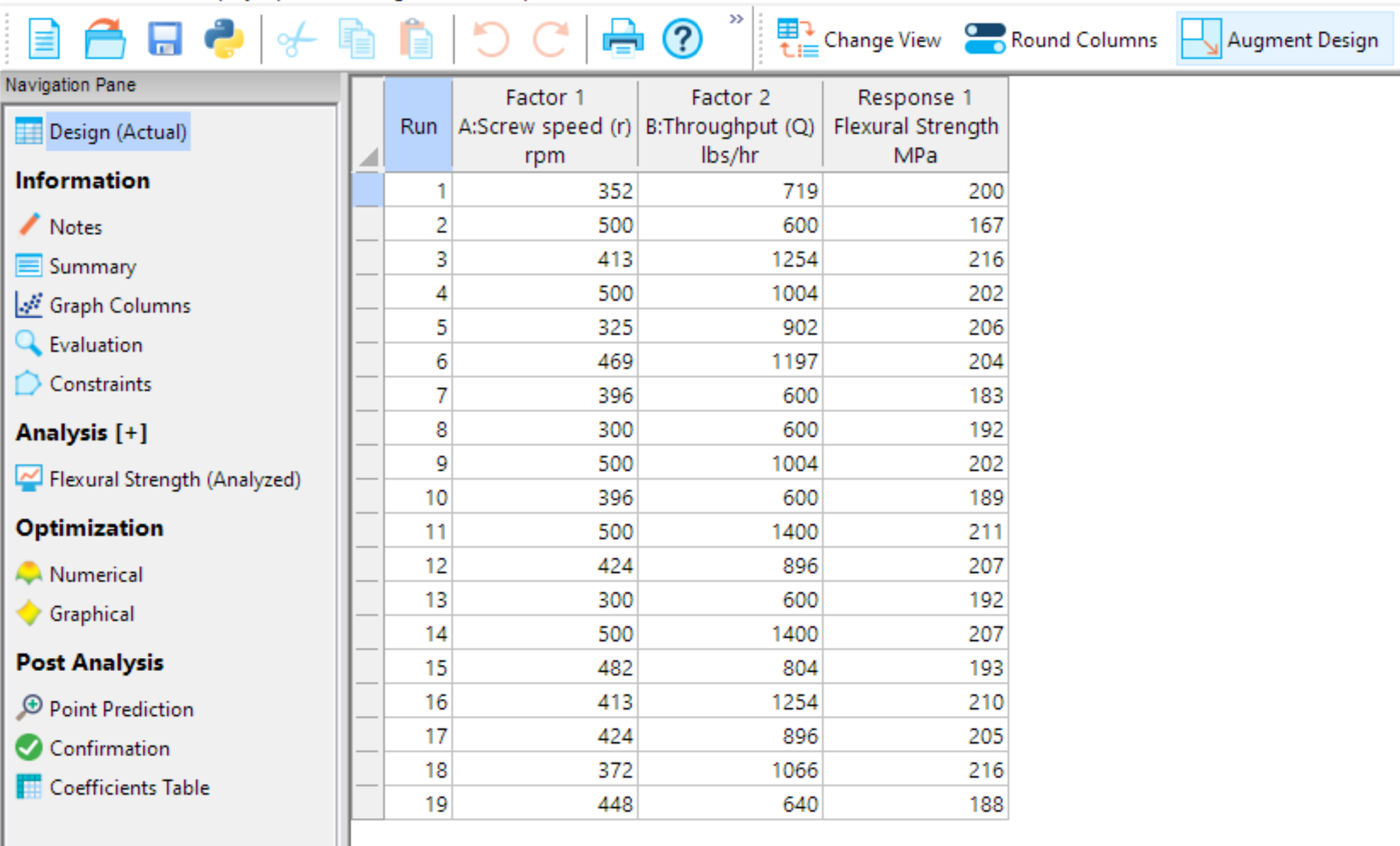
Go to the Help menu, then hover over Tutorial Data and click Reactive Extrusion to load your data. The file comes with the response already modeled. Click the Flexural Strength branch to see the analysis. Press ahead to the Model Graphs and view the Contour plot.

Seeing the ‘hot’ (red) spot in the upper levels of screw speed (A) and throughput (B), it becomes clear that going to higher levels for both these extrusion factors will be beneficial for increasing the strength of the plastic.
Click the Design node and the Augment Design icon to bring up a list of ways to continue experimentation with new runs needed to complete your mission.
Choose Modify Design Space to begin a wizard for shifting the focus of this study. Press ahead (Next) to the entry screen for new factor levels that will expand the current design space and put in more runs in the region already explored that produced desirable results (the hot spot). For A, enter 450 to 550, and for B, type in 1200 to 1600.
Continue moving forward through the wizard by pressing Next several times. Stop at the screen specifying the optimal augmentation. To provide a more precise fit for the hot spot, increase the Additional model points to 4, which, with the other points, brings the total of new runs to 10.

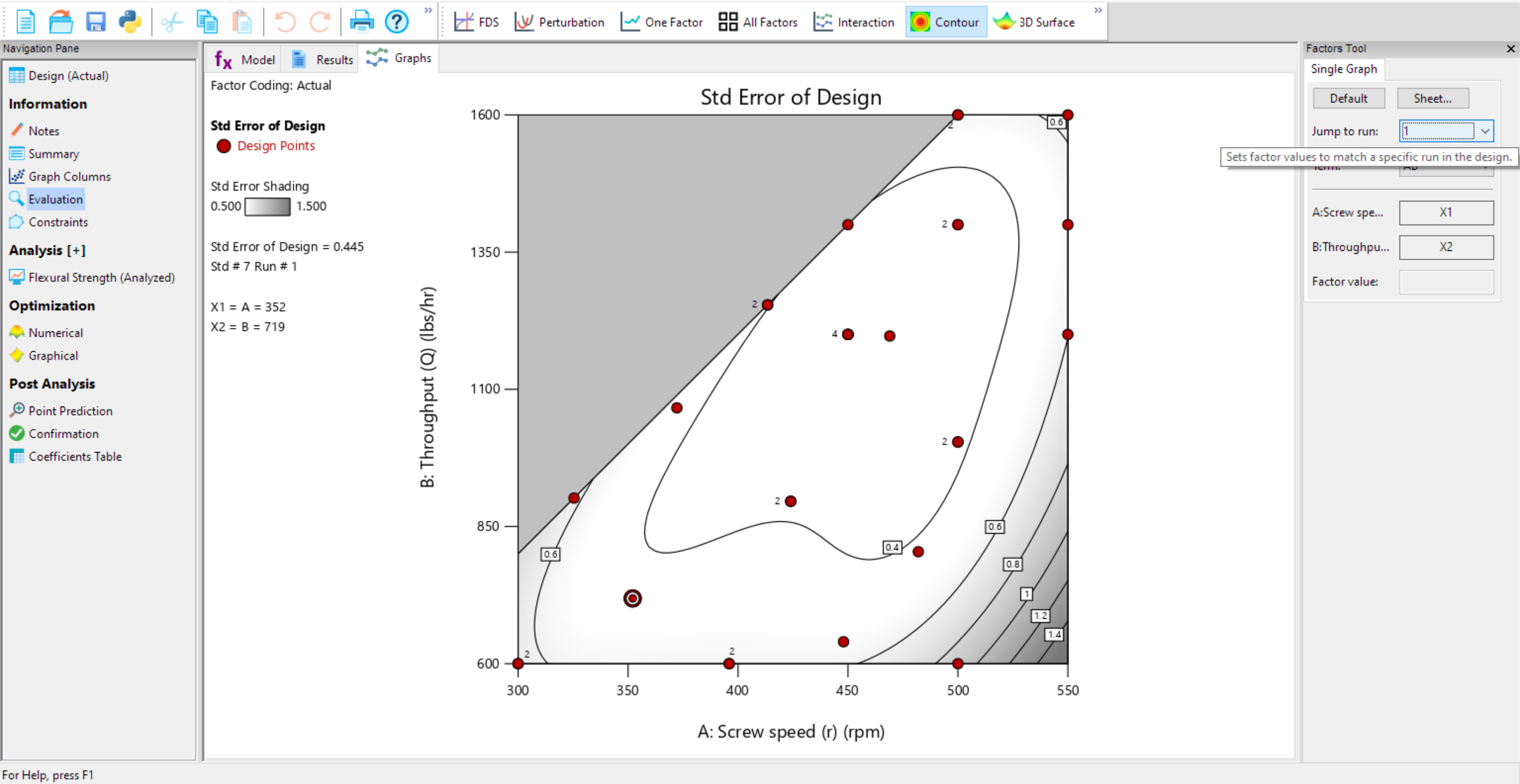
Press Finish to see the results—a second block of new runs. To see where they get located, go to Evaluation, Graphs and bring up the Contour plot of the standard error.

Notice that the ranges of the axes have been set to our new factor lows and highs, so you are looking only at the top corner of the previous space. To see the original design plus the new space, use the Jump to run tool to select run number 1.
Due to the nature of the optimal selection algorithms (best of coordinate or point exchange) your added design points may differ from the one shown above. However, by clicking the Jump to run for 20 through 29 you will see these going to the hot spot at the upper right that the plastic engineers wanted to explore. Mission accomplished by Stat-Ease’s design-space augmentation tool.